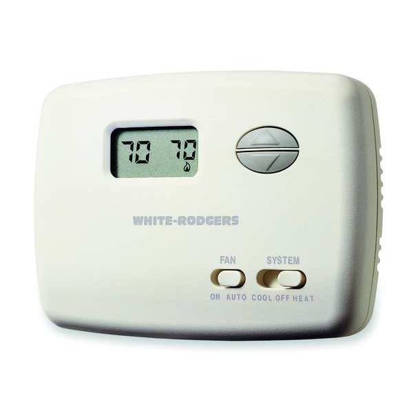
Emerson 1f78-144 Manual Download
1F78-144 | CONFIGURATION AND |
1F78-151 | TYPICAL WIRING DIAGRAMS |
- 1f78 151 User Manual
- Emerson 1f78 151 Pdf
- Emerson Model # 1f78 Thermostat
- Emerson 1f78 144 Wiring Diagram
- Emerson Thermostat Manual 1f78 144
- White Rodgers 1f78 144 Manual
- Emerson 1f78 Programmable Thermostat Manual
- Model # 1f78
- View and Download Emerson 1F78-151 instruction manual online.
- White Rodgers 1E78-144 - Non-Programmable Thermostat, 24 Volt or Millivolt system, Vertical - The vertical 70 Series low-profile design blends narrow width with new home decors. The universal subbase, for use with all 1E78 models, is designed to mount on a 2' x 4' junction box or directly to the wall. There is also an optional wallplate for use in retro-fit applications.
- Nov 21, 2018 The Emerson 1F78-144 single stage thermostat has an easy to read digital display. This non-programmable thermostat works with most single-stage heating and cooling systems. It is for use on 24-volt and millivolt systems.Not compatible with electric baseboard heat and some other systems.
Get White Rodgers 1F78-151 Use and Care Manual. Get all White Rodgers manuals! Sign up to create an account Facebook. The Emerson logo is a trademark and service mark of Emerson Electric Co. Www.white-rodgers.com www.emersonclimate. Don't see a manual you are looking for?
CONFIGURATION
W | RH | B | RC |
G | O | Y | |
W905 | W904 | ||
W905 | |||
Clip for | |||
Hydronic | |||
System | ELEC | GAS | |
W904 | Electric/Gas | ||
Clip for | Switch | ||
Celsius Display | |||
TYPICAL WIRING DIAGRAMS
JUMPER | |||||||
WIRE | |||||||
B | O | Y | G | W | RC | RH | THERMOSTAT |
SYSTEM | |||||||
Cooling | Fan | ||||||
System | Relay | Hot | |||||
24 VAC | 120 VAC | ||||||
Neutral | |||||||
Cool only, 3-wire, single transformer systems
JUMPER
WIRE
THERMOSTAT
B | O | Y | G | W | RC RH |
SYSTEM
NOTE | Fan | Heating |
For 2-wire Heat | only | |
Relay | System | Hot |
attach to RH and W | ||
24 VAC | 120 VAC | |
Neutral | ||
TRANSFORMER | ||
Heat only, 3-wire, single transformer systems
B | O | Y | G | W | RC | RH | THERMOSTAT |
SYSTEM | |||||||
Cooling | Fan | Heating | Hot | ||||
24 VAC | 120 VAC | ||||||
System | Relay | System | |||||
Neutral | |||||||
HEATING TRANSFORMER | |||||||
Hot | |
24 VAC | 120 VAC |
Neutral | |
COOLING TRANSFORMER | |
Heat/cool, 5-wire, two-transformer systems
JUMPER | JUMPER | |
WIRE | WIRE | |
Y | THERMOSTAT | |
B O | G | W RC RH |
SYSTEM
Reversing | Compressor | Fan | Hot | |
Valve* | Contactor | Relay | ||
24 VAC | 120 VAC | |||
* Reversing valve is energized when the | Neutral | |||
system switch is in the COOL position | TRANSFORMER | |||
B O
NOTE
RED jumper wire (provided with thermostat) must be connected between thermostat's RH and RC terminals for proper thermostat operation with this system.
JUMPER
WIRE
THERMOSTAT
Y | G | W RC RH |
SYSTEM
Cooling | Fan | Heating | |
System | Relay | System | Hot |
24 VAC | 120 VAC | ||
Neutral | |||
TRANSFORMER | |||
Heat pump with cool active reversing valve
JUMPER | JUMPER | ||
WIRE | WIRE | ||
Y | THERMOSTAT | ||
B | G | W RC RH |
SYSTEM
Reversing | Compressor | Fan | ||
Valve* | Contactor | Relay | Hot | |
24 VAC | 120 VAC | |||
* Reversing valve is energized when the | Neutral | |||
system switch is in the HEAT position | TRANSFORMER | |||

Heat/cool, 4-wire, single transformer systems | Heat pump with heat active reversing valve |


